HPE H3C JD117B Compatible XFP XFP 10GBASE-SR Transceiver Module
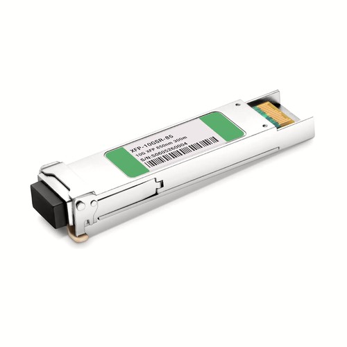
This HPE H3C JD117B compatible transceiver provides XFP connectivity in a hot-swappable XFP package. Its optical design operates at 850nm for up to 300m over OM3 MMF, using LC duplex. Complete parameters and related OEM references help network teams verify host acceptance as well as physical interface fit.
OEM Part Number: JD117BHT Part Number: XFP-10GSR-85
Product Highlights
- Compatible alternative to HPE H3C JD117B
- XFP connectivity at 10Gbps
- Optical wavelength: 850nm
- Specified reach: 300m over OM3 MMF
- LC duplex / MMF interface
- Operating temperature: 0 to 70°C (32 to 158°F)
- Factory compatibility verification and optical performance testing before shipment
Specifications
| HPE H3C Compatible | JD117B |
|---|---|
| Manufacturer | HT |
| HT Part Number | XFP-10GSR-85 |
| Form Factor | XFP |
| Max. Data Rate | 10Gbps |
| Wavelength | 850nm |
| Max. Transmission Distance | 300m over OM3 MMF |
| Connector | LC duplex |
| Transmitter Type | VCSEL 850nm |
| Media | MMF |
| DOM Support | Yes |
| TX Power | -3.5~5.3dBm |
| Receiver Sensitivity | <-13dBm |
| Operating Temperature | 0 to 70°C (32 to 158°F) |
| Protocols | SFP+ MSA Compliant, CPRI, eCPRI |
Applications and Optical Link Design
Typical deployments include switch-to-switch, switch-to-server and aggregation links inside a data hall or between adjacent equipment rooms. The LC duplex interface connects to the specified multimode cabling, and the stated reach depends on fiber grade and link loss. Keep this interface on the matching multimode optical standard rather than connecting it directly to a single-mode wavelength or reach variant.
Before deployment, check the host port type, supported data rate and firmware requirements. The XFP interface configuration must match the remote equipment; sharing a XFP housing alone does not make two transceiver types interoperable.
The multimode channel should use the fiber grade associated with the stated 300m over OM3 MMF reach. Keep the LC duplex end faces clean and avoid tight bends. Different multimode standards are not interchangeable merely because they share a connector.
HPE H3C Compatibility and Factory Testing
The module is checked for host recognition as JD117B, link establishment and diagnostic reporting. Physical cage fit alone is not treated as evidence of compatibility. Equipment model, hardware revision and software release can be reviewed before dispatch where platform behavior is uncertain.
Optical Acceptance, Diagnostics and Handling
For this model, the specified transmit-power range is -3.5~5.3dBm; receiver sensitivity is <-13dBm. A sound acceptance record includes link state, diagnostic temperature, supply voltage and transmit or receive levels where the host exposes them. Compare the readings with the stated ranges rather than treating any received light as proof of adequate margin. Persistent alarms or borderline values should trigger an end-face and complete-channel inspection. Before every insertion, keep dust caps in place until the patch lead is ready, avoid touching the optical end face and use an appropriate inspection and cleaning procedure. Do not look into an active optical interface.
Interoperability and Host Configuration
Check three layers before deployment: host acceptance of the module identity, port support for the stated rate, and a matching optical standard at the remote interface. For breakout operation, confirm lane configuration too. Similar-looking cages can behave differently across speeds and firmware settings. For this model, the principal parameters are data rate 10Gbps, wavelength 850nm, rated reach 300m over OM3 MMF.
Ordering Information
Use JD117B as the compatibility cross-reference and XFP-10GSR-85 as the HT ordering identity. Keep other reaches or wavelength directions on separate order lines. Neutral labels, customer packaging and project-specific compatibility review are available on request.
Shipping and Lead Time
Standard configurations normally ship within one to three working days, with production lead times confirmed for larger quantities. International courier, air freight and sea freight are available; customer courier accounts and nominated forwarders are accepted.
Quality Assurance and Packaging
Each JD117B compatible module is inspected, powered up and functionally checked before protective packing. Dust caps and individual trays shield the interface during transport. Customer references, rack groups and project packing lists can be added for volume orders.
Frequently Asked Questions
Is this an original HPE H3C transceiver?
No. It is an HT-manufactured compatible alternative for equipment that specifies JD117B, not an original HPE H3C-branded module.
Which fiber and connector are required?
Use LC duplex with MMF. The specified maximum reach is 300m over OM3 MMF, subject to fiber quality and total link loss.
Can it be mixed with another wavelength or reach version?
Only when the two ends share the same optical standard, wavelength plan and supported data rate. Check the exact part numbers and link budget rather than relying only on the module form factor.
Fiber Optic Cables
Fiber Transceivers
Get a quick quote
 Lisa Zhou
 Steve Yan
 Flora Luo
 Stone Wang
 Allen Hu
About us
China Factory:No 168 Golden Ground Industrial Area;Philippines Address:Makati City,Metro Manila, Philippines