MMC-24 APC to MTP-24 UPC Jumper, 24 Fibers, OM4
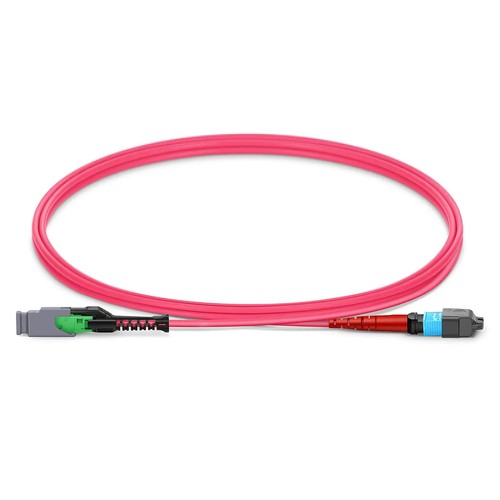
Projects in the Philippines benefit from keeping the configuration, branch identification and installation requirement consistent across every participating site. The 24FMMCMTPOM4 jumper combines a 24-fiber MMC APC female interface with a 24-fiber MTP UPC female interface. This mixed-polish OM4 item is suited to channels that specifically require APC at the MMC side and UPC at the MTP side. It should not be treated as interchangeable with the APC-to-APC configuration, even though the two products share the equivalent fiber count and connector families.
Product Highlights
- MMC Female to MTP® Female, 24 Fibers
- OM4 50/125μm, bend-insensitive fiber
- MMC insertion loss ≤0.35dB, return loss ≥40/20dB (MMC/MTP®)
- Jumper Polarity wiring scheme
- 2.5mm Plenum (OFNP) cable
- Standard length options: 1m (3ft), 2m (7ft), 3m (10ft)
Specifications
| Part Number | 24FMMCMTPOM4 |
|---|---|
| Manufacturer | HT |
| Connector A | US Conec MMC Female (Non-Pinned) |
| Connector B | US Conec MTP® Elite Female (Non-Pinned) |
| Polish Type | APC to UPC |
| Glass Fiber | Bend Insensitive Fiber |
| Fiber Mode | OM4 50/125μm |
| Wavelength | 850/1300nm |
| Fiber Count | 24 Fibers |
| Polarity | Jumper Polarity |
| Cable Outside Diameter (OD) | 2.5mm |
| Cable Jacket | Plenum (OFNP) |
| Min. Bend Radius (Optical Fiber) | 7.5mm |
| Min. Bend Radius (Fiber Cable) | 20/10D (Dynamic/Static) |
| Tensile Strength (Long Term) | 30N |
| Tensile Strength (Short Term) | 100N |
| Insertion Loss | ≤0.35dB |
| Return Loss | ≥40/20dB (MMC/MTP®) |
| Attenuation at 850nm | ≤2.3dB/km |
| Attenuation at 1300nm | ≤0.6dB/km |
| Operating Temperature | -10 to 60°C (14 to 140℉) |
| Storage Temperature | -10 to 70°C (14 to 158℉) |
Why the polish combination matters
APC and UPC end faces have separate geometry and reflection behavior. They should never be forced as one system in a mating adapter. This jumper deliberately places APC on the MMC connector and UPC on the MTP Elite connector; as a result, the surrounding optical path must present the matching APC and UPC interfaces. Checking the polish at each end is as important as confirming 24-fiber compatibility.
Twenty-four fibers in a compact route
One 2.5mm OFNP jumper carries all 24 fibers, reducing cable bulk compared with twelve duplex patch leads. Both connectors are female and non-pinned, and factory jumper polarity controls the internal map. The MMC side gives at least 40dB return loss; the UPC MTP side is rated at 20dB minimum, with 0.35dB maximum insertion loss for the factory-built assembly.
Ordering and installing the correct version
Standard choices are 1m (3ft), 2m (7ft) and 3m (10ft), plus non-standard lengths in feet or meters. Identify this APC-to-UPC configuration legibly in rack documentation to distinguish it from APC-to-APC patch leads. During site work, review the ferrules, follow the key orientation and observe the 7.5mm minimum optical-fiber bend radius around the MMC and MTP boots.
Ordering and Factory Support
Quote 24FMMCMTPOM4 and explicitly validate the APC-to-UPC need, length and unit count. A simple port plan showing the MMC and MTP mating interfaces will help prevent an accidental substitution with the APC-to-APC configuration. Customers in the Philippines can include multi-site labeling or documentation requirements when requesting a project quotation.
Fiber Optic Cables
Fiber Transceivers
Get a quick quote
 Lisa Zhou
 Steve Yan
 Flora Luo
 Stone Wang
 Allen Hu
About us
China Factory:No 168 Golden Ground Industrial Area;Philippines Address:Makati City,Metro Manila, Philippines